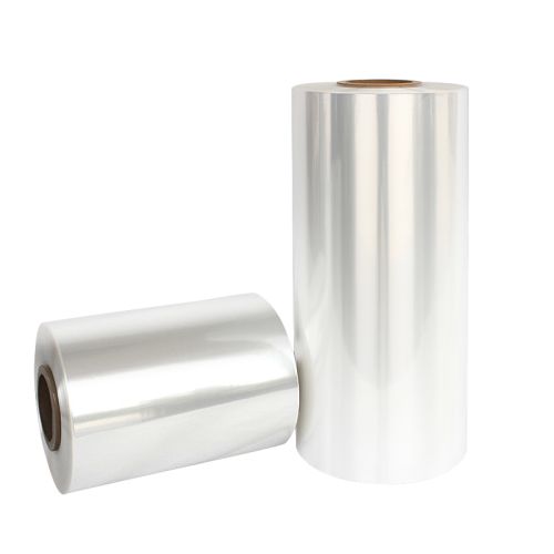
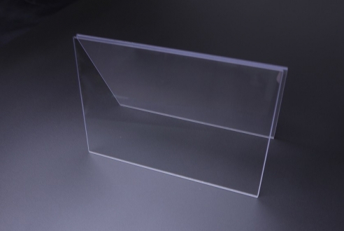
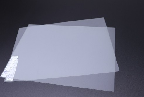
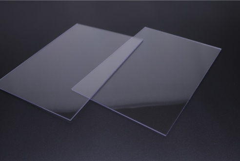
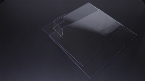
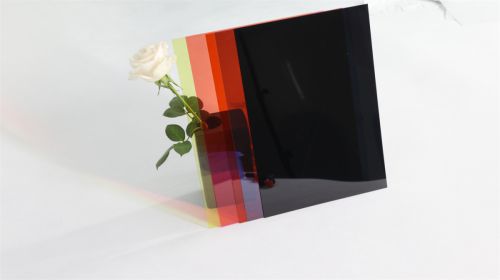
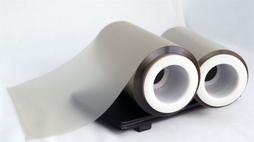
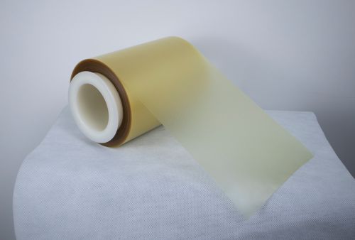
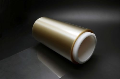
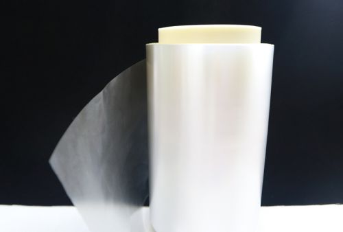
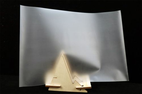
A black insulation barrier inside a power supply may separate conductors, block light, protect components, support labels, and contribute to a flammability design. Black Flame-Retardant PC Film for Power Supplies should not be approved from color or a material rating alone. Cutouts, folds, fasteners, sharp edges, creepage distance, adhesive, heat sources, and the final enclosure determine whether the barrier works. The film selection must follow the electrical and fire-safety analysis of the complete device.
Convert the Hazard Analysis into Film Requirements
Identify voltage, transient events, pollution degree, required clearance and creepage, temperature near components, expected life, flame requirement, mechanical contact, service access, and enclosure design. Determine whether the film is basic insulation, supplementary insulation, a flame barrier, a light shield, or a combination.
The role controls thickness, geometry, dielectric test, flammability requirement, edge protection, and inspection. A generic power supply insulation film description is not enough for engineering approval.
Confirm the Exact Flame-Retardant Grade
The official black flame-retardant PC film product page identifies halogenated and non-halogen options, a 0.125–2 mm thickness range, width up to 1200 mm, and UL 94 V-0 performance for the listed product family. It also provides reference mechanical, thermal, electrical, and shrinkage data.
These values are grade- and thickness-dependent. Obtain the current certificate and datasheet for the ordered code. Do not assume that a color match, another thickness, or a modified formulation carries the same rating.
Dielectric Performance Depends on the Cut Part
Black PC electrical insulation is commonly die cut, folded, scored, printed, or laminated with adhesive. Each operation can reduce effective thickness or create stress at an edge. Burrs, holes, slots, embossed features, and metal fasteners affect electric-field concentration.
Test representative parts, not only flat film. Inspect the minimum material path around cutouts and the way the part sits after assembly. If adhesive holds the barrier, verify bond, creep, temperature, flame behavior, and dielectric compatibility.
Heat and Forming Define the Assembly Window
PC provides useful toughness and forming behavior, but heat from transformers, switching devices, resistors, and restricted airflow can change dimensions or accelerate adhesive aging. Map the actual temperature distribution and include abnormal operating conditions required by the project.
For folded or thermoformed barriers, evaluate springback, whitening, cracking, thickness at bends, and retention after thermal cycling. A flame retardant plastic film should remain correctly positioned throughout service; passing an initial fit check is insufficient.
Incoming Control Must Match Safety-Critical Use
The purchase order should identify product code, formulation type, color, texture, thickness and tolerance, width, surface orientation, roll or sheet form, certification revision, lot traceability, and change-control requirements. Define checks for identity, thickness, appearance, contamination, roll damage, and certificate matching.
Production validation should include die-cut yield, forming, assembly time, adhesive cure, dielectric tests, thermal cycling, vibration if relevant, and the device-level safety program. Retain parts and material linked to each lot for failure analysis.
Thickness Tolerance Affects Clearance and Assembly Fit
Nominal thickness influences dielectric margin, stiffness, fold behavior, slot fit, and the space available around components. Gauge variation can cause a part to buckle, interfere with a cover, or move closer to a conductor. Measure critical locations on the converted part, especially after forming or embossing.
Engineering drawings should define thickness where it matters rather than applying an unnecessarily tight global limit. Coordinate film tolerance with die-cut, fold, adhesive, and enclosure tolerances through a stack-up analysis.
Control Cleanliness and Edge Quality
Metal particles, carbonized cutting debris, oil, and damaged edges can reduce insulation reliability. Review die condition, cutting method, cleaning, packaging, and handling. Black film can make some contamination harder to see, so inspection lighting and magnification should match the defect risk.
Protect finished parts from dust and deformation during storage. If laser cutting is used, examine heat-affected edges and residue; if steel-rule cutting is used, monitor burrs and die wear.
Evaluate Halogen and Non-Halogen Options Separately
The product family includes halogenated and non-halogen formulations. They should be treated as different grades with separate certificates, processing behavior, color, and property data. A sustainability or customer specification may restrict formulation choice.
Qualify the selected formulation on the actual device and keep its code under change control. Do not substitute formulations based only on the same color and flame classification.
Review Marking and Printing as Functional Processes
Part numbers, warning text, or alignment marks may be printed on the PC barrier. Confirm ink adhesion, legibility, abrasion resistance, chemical exposure, and any effect on flammability or dielectric surfaces. Keep printing away from required electrical contact or bonding zones when specified. Test marked parts after forming and thermal cycling because ink cracking can indicate local strain. Artwork revision and ink changes should be included in production change control.
An RFQ for UL94 V-0 polycarbonate film should identify the exact rated grade and thickness. The converted die-cut PC insulation barrier remains subject to device-level approval.
FAQ
Does UL94 V-0 mean the film is approved for every power supply?
No. The rating applies to a specific material and thickness under its test conditions. Device design and applicable safety standards still control approval.
Can the thinnest available PC film be used to save space?
Only if dielectric, mechanical, forming, flammability, and manufacturing tolerances remain adequate in the finished part.
Should dielectric strength be tested after die cutting?
Yes when cut edges, folds, embossing, or assembly stresses could affect the insulation path.
Why choose black PC rather than transparent PC?
Black film may provide opacity and visual integration, but color should not override the required electrical, thermal, mechanical, and flame properties.
Black Flame-Retardant PC Film for Power Supplies: Approval Focus
Black Flame-Retardant PC Film for Power Supplies should be selected from the device hazard analysis and qualified as a converted barrier. Confirm the exact rated grade, then test die cutting, forming, dielectric separation, heat exposure, and assembly retention.